- Home
- Project Solutions
- FBD Contol System
FBD Contol System
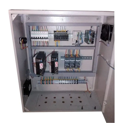
FBD (Function Block Diagram) control system is a graphical programming language used for programming and controlling programmable logic controllers (PLCs) and other automation devices. It is used in a variety of industries, including manufacturing, process control, and building automation. In an FBD control system, the control logic is represented graphically as blocks connected by lines, with each block representing a specific function, such as AND, OR, NOT, timer, or counter. The blocks are connected to input and output signals, and the lines represent the flow of information between the blocks.
The main components of an FBD control system include:
Programmable logic controller (PLC): This is the main component of the system, responsible for executing the control logic and controlling the process.
Input/Output (I/O) modules: These are devices that interface between the PLC and the process being controlled, allowing the PLC to receive input signals and control outputs.
Human-machine interface (HMI): This is the interface between the operator and the control system, providing a graphical representation of the process and allowing the operator to make adjustments to the control logic.
Software: This is the program that is used to create and edit the FBD control logic.
The FBD control system works by executing the control logic, which continuously monitors the input signals and makes decisions based on the set conditions and algorithms. The decisions are then carried out by controlling the outputs, allowing the process to be automated and optimized. Litrols offer an FBD control system that has a simple and intuitive way to program and control automation devices, allowing for efficient and effective control of various processes.